Page 167 - IGUS Linear
P. 167

drylin  T rail guides | Design rules                                                                                     drylin  T rail guides | Technical data
                                                                                                                                           ®
                   ®


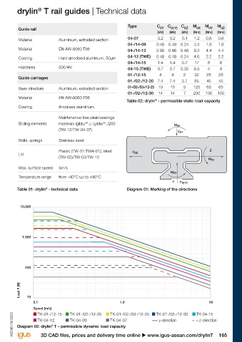
        Design tip                                            Version with floating bearing in z-direction                       Guide rail                                            Type          C 0Y  C 0(-Y)  C 0Z  M 0X  M 0Y  M 0Z
        The compensation of parallelism errors up to a maximum                                                                                                                                        [kN]  [kN]  [kN]  [Nm]  [Nm]  [Nm]
        of 0.5mm between mounted rails is possible with a fixed/  1   Rail                                                       Material            Aluminium, extruded section       04-07          0.2   0.2   0.1  1.2   0.6   0.6
        floating bearing. During installation, take care that the   2   Sliding elements                                         Material            EN AW-6060 T66                    04-/14-09     0.48  0.48  0.24  3.4   1.8   1.8
        floating bearing has approximately the same clearance on   3   Carriage with fixed bearings                                                                                    04-/14-12     0.96  0.96  0.48  9.2   4.4   4.4
        both sides.                                            4   Carriage with floating bearings                               Coating             Hard-anodised aluminium, 50µm     04-12 (TWE)   0.48  0.48  0.24  4.6   2.2   2.2
        In the adjacent designs you can see the version of the fixed/   LLZ or LLY                                               Hardness            500 HV                            04-/14-15      1.4   1.4   0.7   17    8     8
        floating bearing system recommended by us.                                                                                                                                     04-15 (TWE)    0.7   0.7  0.35  8.5    4     4
        The mounting surfaces of the rails and guide carriages                                                                   Guide carriages                                       01-/12-15      4     4     2     32    25    25
        should be very flat (e.g. machined surface) to prevent                                                                                                                         01-/02-/12-20 7.4    7.4  3.7    85    45    45
        twisting in the system. Small discrepancies in the mounting   Horizontal version with floating bearing in z-direction    Base structure      Aluminium, extruded section       01-/02-/03-/12-25 10  10   5    125    65    65
        surfaces can be compensated up to a certain amount                                                                       Material            EN AW-6060 T66                    01-/02-/12-30  14    14    7    200   100   100
        (0.5mm) by a greater clearance adjustment. The clearance                                                                                                                      Table 02: drylin  - permissible static load capacity
                                                                                                                                                                                                    ®
        adjustment is possible only in unloaded state. If you have                                                               Coating             Anodised aluminium
        any questions on design and/or assembly, please make
        use of our technical support.                         Horizontal version with floating bearing in the                                        Maintenance-free plain bearings
                                                                                                                                                                  ®
                                                                                                                                                                           ®
                                                              y-direction and lateral guide carriage                             Sliding elements    materials iglidur  J, iglidur  J200                      M 0X
               Technical details on floating bearings                                                                                                (TW-12/TW-04-07)
               u Page 50                                                                                                                                                                                        C 0Y
               The 2:1 Rule u Page 50                                                                                            Bolts, springs      Stainless steel


                                                                                                                                                     Plastic (TW-01/TWA-01), steel       C 0Z                                  Z
        Installation drylin  T linear guide system                                                                               Lid                 (TW-02)/TW-03/TW-12
                           ®
        Make sure to assemble the side of the carriage saying                                                                                                                                                                  M 0Z
        "Reset Clearance" onto the rail first (see picture).                                                                     Max. surface speed  5m/s
                                                                                                                                                                                                            M 0Y
                                                                                                                                 Temperature range   from -40°C up to +90°C
                                                                                                                                                                                                             Y  C 0(-Y)

                                                                                                                                 Table 01: drylin  - technical data                   Diagram 01: Marking of the directions
                                                                                                                                              ®


                                                                                                                                  10.000


                                                                                                                                   1.000
        TW series, adjustable clearance                       TWA series, automatic


        Tightening torque for drylin  metallic screws         Floating bearing clearances for drylin  T
                                                                                                      ®
                                     ®
         Metric thread   tightening     Recommended           miniature guides
         (Da)              torque      tightening torque      LLZ:   Floating bearing in z-direction                                100
                            [Nm]             [Nm]             LLY:  Floating bearing in y-direction
         M3               0.5 - 1.1           0.7
         M4               1.0 - 2.8           1.5              Floating   TW-04-07 TW-04-09 TW-04-12 TW-04-15
         M5               2.0 - 5.5           3.0              bearing                                                            Load F [N]
         M6               4.0 - 10.0          6.0              clearances                                                            10
         M8               8.0 - 23.0         15.0              LLY           –        0.4      0.5       0.7                            0,1                                        1,0                                         10
         M10             22.0 - 46.0         30.0              LLZ          0.4      0.4       0.5       0.7                            Speed [m/s]

        Minimal screw-in depth for aluminium and zinc                                                                                      TK-01-/12-15    TK-01-/02-/12-20    TK-01-/02-/03-/12-25   TK-01-/02-/12-30   TK-04-15
                                                                                                                                                                               TK-04-07
                                                                                                                                           TK-04-12
                                                                                                                                                           TK-04-09
        die-casting parts: 1.5 x Da                                                                                ASEAN 09/2023  ASEAN 09/2023  Diagram 02: drylin  T - permissible dynamic load capacity   y-direction   z-direction
                                                                                                                                                 ®
        164 Online tools and more information u www.igus-asean.com/drylinT                                                                  3D CAD files, prices and delivery time online u www.igus-asean.com/drylinT              165
   162   163   164   165   166   167   168   169   170   171   172